In this in-depth, 86 step tutorial, you will learn how to create a stylish liquid looking logo using Next Limit’s Realflow. Using Cinema 4D as the main 3D package, you will learn how to integrate Illustrator and After Effects to efficiently design, simulate, export, and render your final animation.
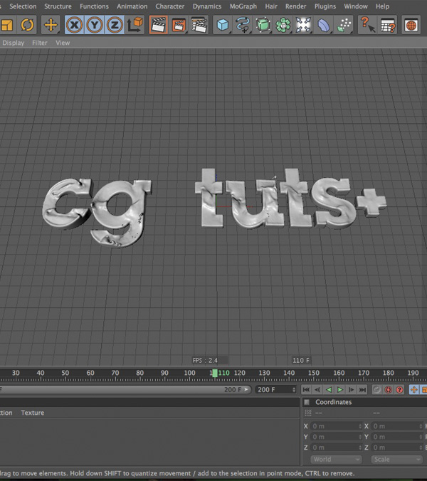
Final Effect Preview
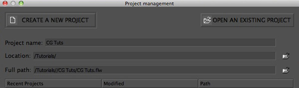
Step 1
First things first. Since you are going to be using a wide array of applications, you need your file structure to stay clean and concise. Open Realflow and create and new project calling it CG Tuts or any other name you would like.
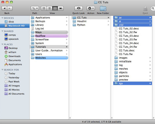
Step 2
Open Finder, and navigate to your ‘CG Tuts’ realflow folder. Create four new folders, rename them to ‘ae’, ‘ai’, ‘c4d’, and ‘tga’.
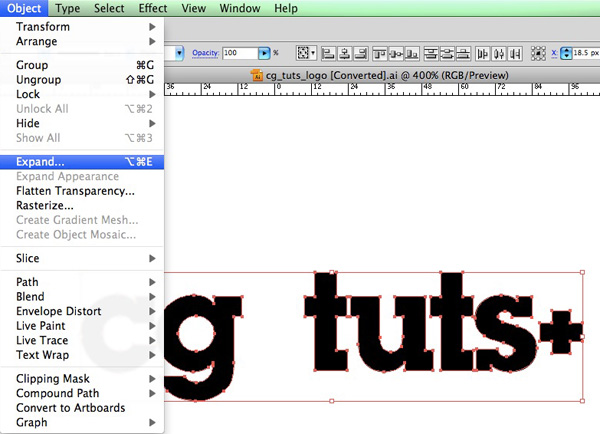
Step 3
Open Illustrator and type out the name of your logo. Once you have typeset your logo and you are happy with its layout, select your text object and expand it by choosing ‘Object’, ‘Expand’
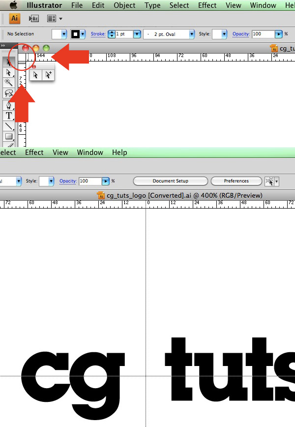
Step 4
Click and drag your artboard’s co-ordinates box to center your artboard so that when you import your Illustrator logo’s splines into Cinema 4D they will also be centered.
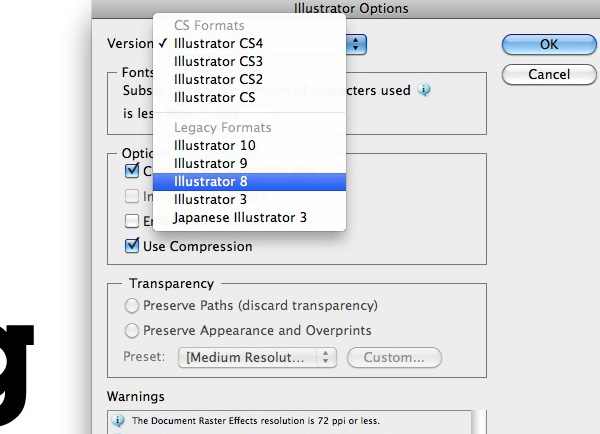
Step 5
Save your file as an Illustrator 8 formatted file inside the ‘ai’ folder you made earlier.
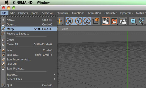
Step 6
Select ‘File’, ‘Merge’ and select your Illustrator file. Click ‘Open’. Save your file inside of the ‘c4d’ folder you made earlier.
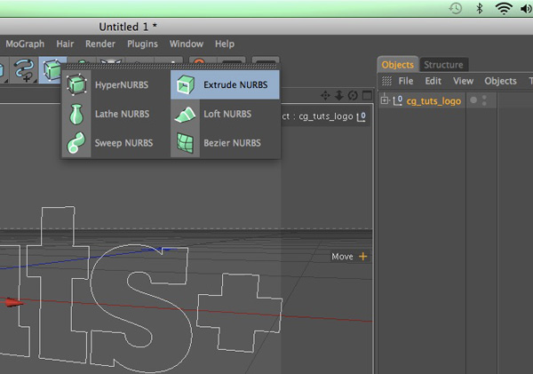
Step 7
With your logo object selected, hold ‘Option’ (‘Alt’ on a PC), and create an ‘Extrude Nurbs’ object. (Holding the ‘Option’ key with an object selected before you create anything inside of Cinema will make it the ‘parent’ of that selected object)
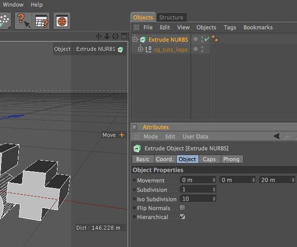
Step 8
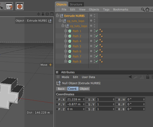
Select the Extrude Nurbs ‘Object’ tab and check the ‘Hierarchical’ option box.
Step 9
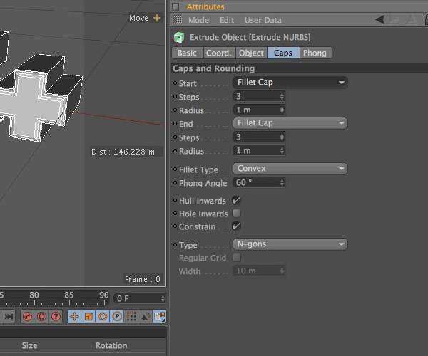
Select the ‘Caps’ tab and change both the ‘Start’ and ‘End’ options to ‘Fillet Cap’ with 3 ‘Steps’ and 1 for the ‘Radius’. Make sure ‘Constrain’ is checked as well.
Step 10
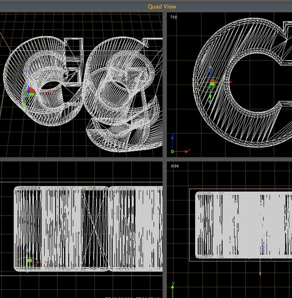
Hit ‘C’ on your keyboard to make the Extrude Nurbs object editable. Select the ‘+’ sign to the left of your Extrude Nurbs object until you can see the individual Extrude Nurbs objects created for each individual letter.
Step 11
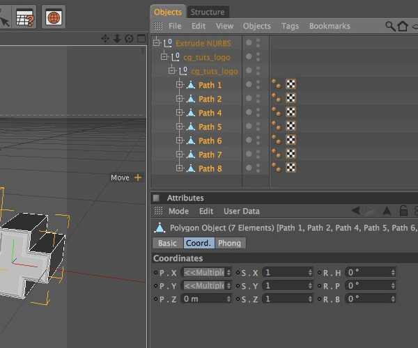
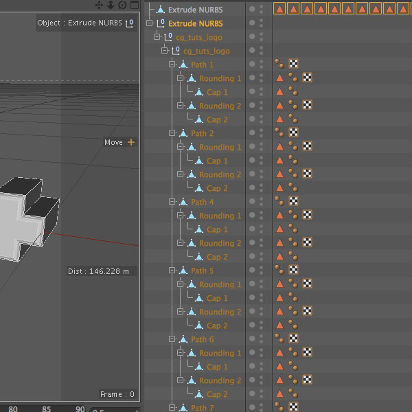
Select all your ‘Paths’ and hit the ‘C’ key again. This will not complete the process of making all out text editable.
Step 12
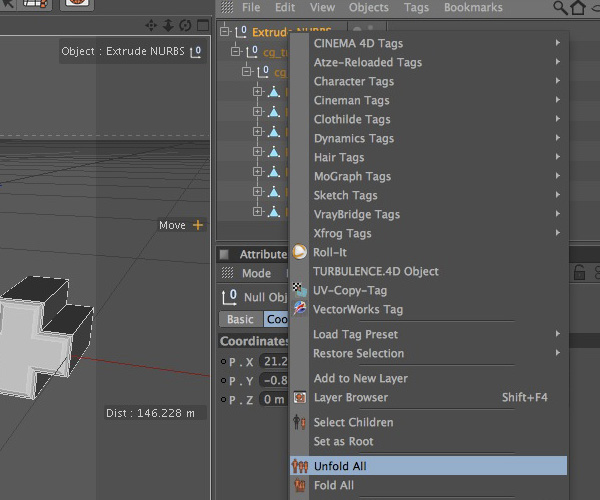
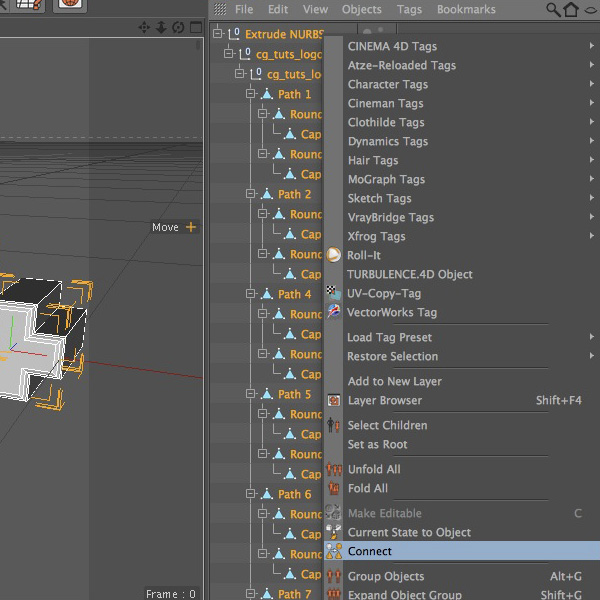
Right click on your Extrude Nurbs object and select the ‘Unfold All’ option.
Step 13
Select all the objects inside the ‘Object Manager’, right click on one of them, and select ‘Connect’. This will create a single piece of geometry.
Step 14
Delete all the ‘Set Selections’ (the orange triangles) and the old Extrude Nurbs under our newly ‘Connected’ one.
Step 15
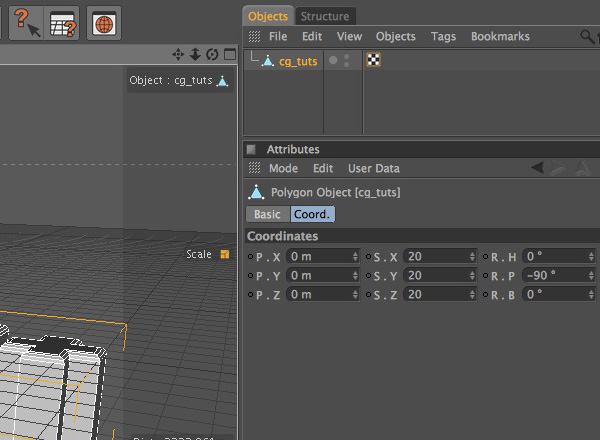
Rename your Extrude Nurbs object to ‘cg_tuts’ or the name of your logo. Add a -90 degree rotation on the ‘Pitch’ option of your objects co-ordinates. Scale the text 20 times in all three axis.
Step 16
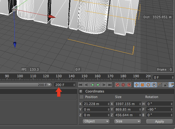
Change your ‘Timelines’ default length from ‘90 frames’ to ‘200 frames’.
Step 17
Time to export to Realflow. With your text selected, click on ‘Plugins’, ‘Next Limit’, ‘[NL] Realflow SD Export’.
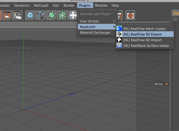
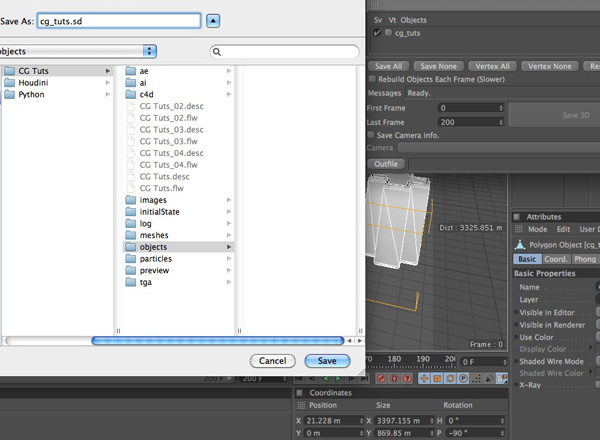
Step 18
Click on ‘Save All’. Then click on ‘Outfile’ which will bring up a window asking where to save your exported ‘SD’ file and what you would like to name it. Navigate to your ‘objects’ folder and click on ‘Save’.
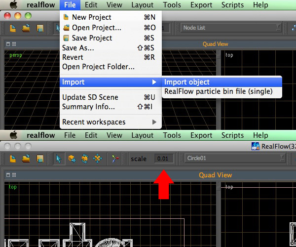
Step 19
Back to Realflow. Select ‘File’, ‘Import’, ‘Import Object’. Select the ‘.sd’ file you just output through Cinema 4D and click ‘Open’. Set your scenes scale ‘0.01′.
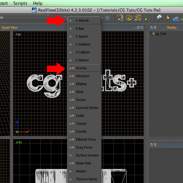
Step 20
Lets add some key important ‘Daemons’ to the scene. Click on the triple arrow symbol which contains all the ‘Daemons’. Add a ‘Gravity’ and a ‘k Volume’ daemon to your scene.
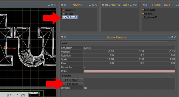
Step 21
Select your ‘k_Volume’ node and click on ‘Fit To Scene’. This will prevent any stray particles from creating an unstable simulation.
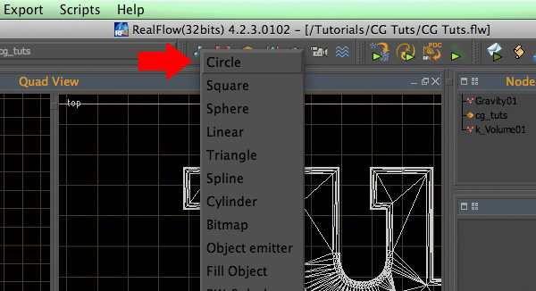
Step 22
Click on the "three blue dots" to the left of the ‘Daemons’ which is where you will find all your ‘emitters’. Add a ‘circle’ emitter.
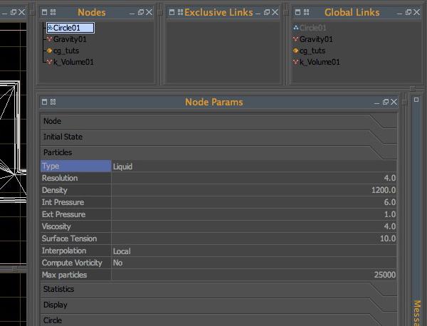
Step 23
In the ‘Nodes Params’ pallete, under the ‘Particles’ tab, change the defaul settings to, ‘Resolution 4.0′, ‘Density 1200.0′, ‘Internal Pressure 6.0′, ‘External Pressure 1.0′, Viscosity 4.0′, Surface Tension 10.0′, and finally ‘Max Particles 25000′. The Max Particles setting sets your emitters maximum amout of particles that can be emitted per emitter, and since you will be using about ‘20′ emitters, the ‘Max Particles’ value is going to change from each set of emitters because each letter only needs a cetain amount of particles together to reach the same height as the other letters, keeping a consistant looking depth.
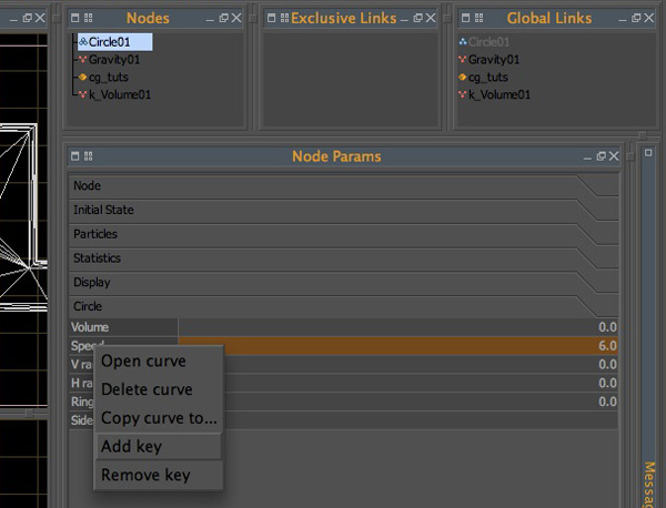
Step 24
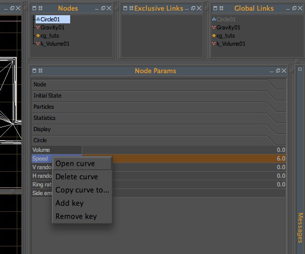
Click on the ‘Circle’ tab and change the ‘Speed’ to 6.0. Righ click on the word ‘Speed’ and add a keyframe at Frame ‘0′. Repeat this step for frames ‘10′ and ‘20′.
Step 25
Right click on ‘Speed’ one more time and click on ‘Open Curve’.
Step 26
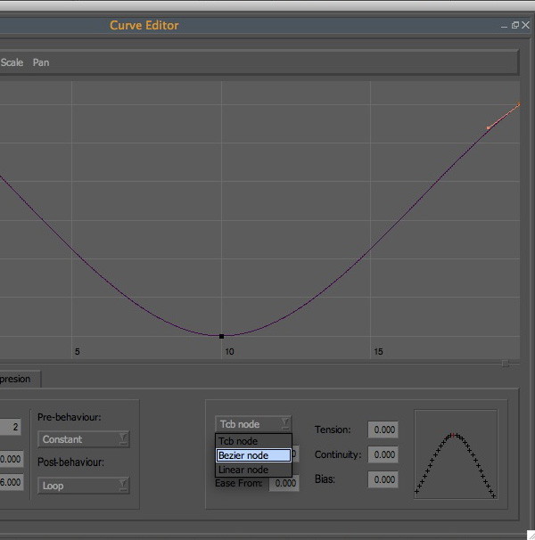
Select ‘Fit H’ and ‘Fit V’ to fit your curve both horizontally and vertically. Select the last keyframe which is at frame ‘20′, and change its node from ‘Tcb Node’ to ‘Bezier Node’.
Step 27
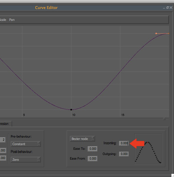
Change the ‘Incoming’ curve value from ‘9.000′ to ‘0.000′. Repeat steps 26 and 27 for the keyframe on frame ‘0′ changing the ‘Outcoming’ curve value from ‘-9.000′ to ‘0.000′. Repeat step 26 for the final keyframe on frame ‘10′.
Step 28
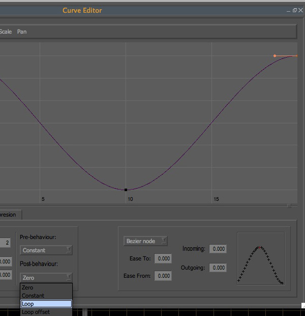
Select the keyframe at frame ‘20′ and change the ‘Post-Behavior’ from ‘Zero’ to ‘Loop’. This will make your curve loop through its keyframes infinitely.
Step 29
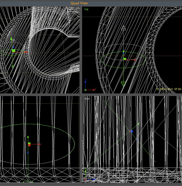
Select your emitter and postition it inside the first letter of your logo, making sure that the emitter is placed near the bottom of the logo, and rotated around a -45 to a -50 degree angle.
Step 30
Duplicate your emitter and repeat steps 24 – 29. Make sure to rotate your new emitter to the opposite of value of your first one. Position it away from the first one so they are not intersecting one another too much.
Step 31
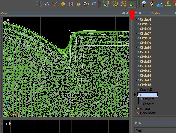
Now you are ready for some simulations. Hit the ‘Simulate’ button and let it rip.
Step 32
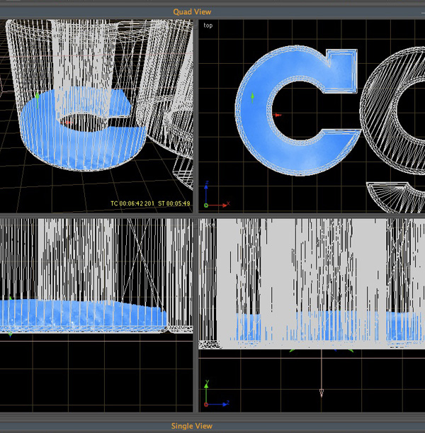
Your liquids should look like something similar to the image below on the final frame.
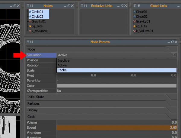
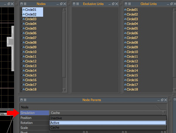
Step 33
Select both your emitters and change their ‘Simulation’ node from ‘Acitve’ to ‘Cache’. This will help you visualize how many particles have been emitted inside of the previous letters and help you with matching the depth so you have an even logo.
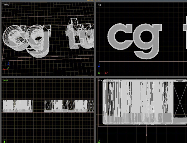
Step 34
Repeat steps 30 -33. Your results should look like something to the image below.
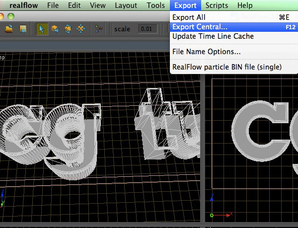
Step 35
Select ‘Export’, ‘Export Central’.
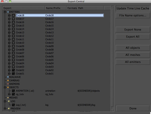
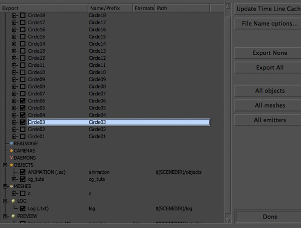
Step 36
Uncheck all of the emitters that are not a part of your first letter of your logo. Select ‘Update Time Line Cache’. Hit ‘Done’.
Step 37
With both of your emitters seleted, change their ‘Simulation’ nodes and change them from ‘Cache’ to ‘Active’.
Step 38
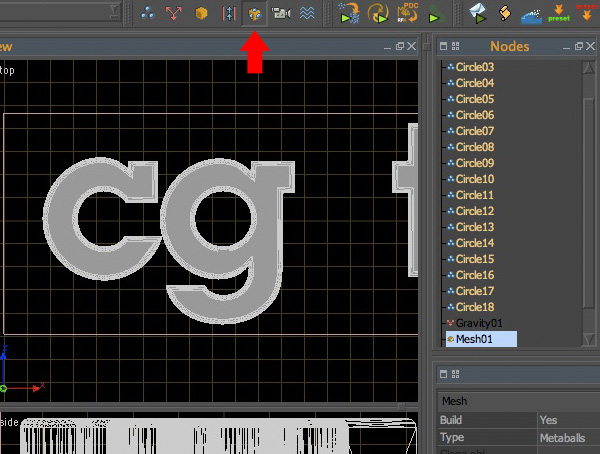
Select the ‘Add Mesh’ icon to add a mesh to your scene.
Step 39
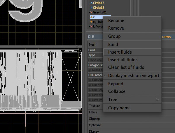
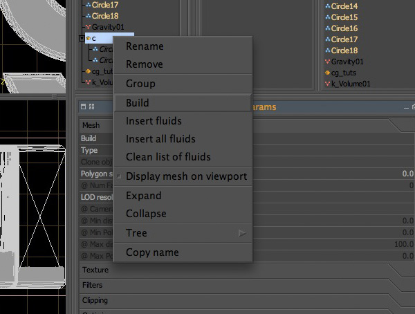
Rename your ‘Mesh’ to something appropriate like the letter ‘c’ or whatever the name is of the first letter in your logo. Right click on your ‘c’ mesh and select ‘Insert Fluids’.
Step 40
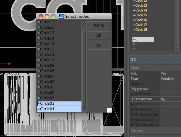
Select both your emitters and click on ‘Ok’.
Step 41
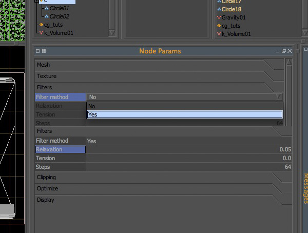
Select the ‘Filters’ tab and change the ‘Filter Method’ from ‘No’ to ‘Yes’. Change the ‘Relaxation’ from ‘0.1′ to ‘0.05′.
Step 42
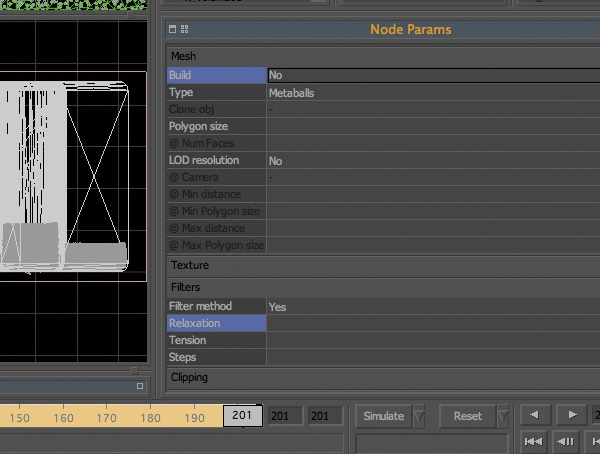
Right click on your mesh and select ‘Build’.
Step 43
With you mesh node selected, click on the ‘Build Meshes’ script which will build a mesh for every single frame in your timeline.
Step 44
Change your meshes ‘Build’ node from ‘Yes’ to ‘No’. Go back to ‘Export Central’.
Step 45
Turn off your mesh, and both of your emitters. Turn on the next set of emitters which pertain to the next letter in your logo. Select ‘Update Time Line Cache’ and hit ‘Ok’.
Step 46
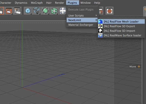
Repeat steps 37 – 45. Open a new document inside of Cinema 4D. Click on ‘Plugins’, ‘NextLimit’, ‘[NL] RealFlow Mesh Loader’.
Step 47
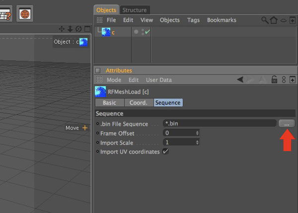
Rename the mesh loader object to the name of the first letter of your logo. Select the ‘Sequence’ tab and click on the ‘…’ icon.
Step 48
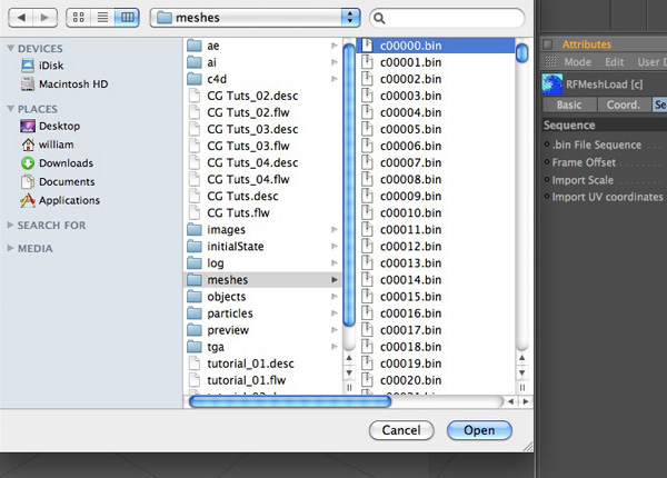
Navigate to your ‘CG Tuts’ folder and click on your ‘meshes’ folder. Select your ‘c00000.bin’ mesh and click ‘Open’.
Step 49
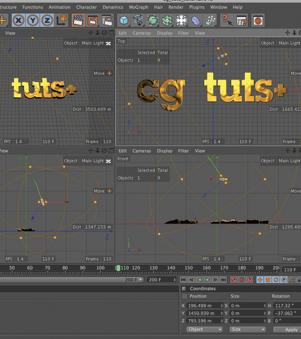
Repeat Steps 46 – 48 for the remaining letters of your logo. Change your ‘Timelines’ default length from ‘90 frames’ to ‘200 frames’. Your workspace should look something similar to the image below.
Step 50
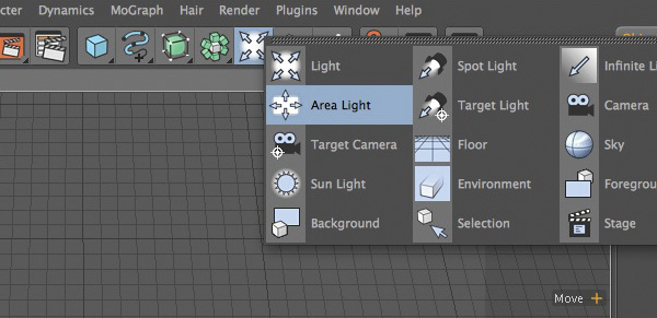
The following steps derived from free downloadable files over at HYPA.TV. You can either download the lighting presets and scale the ‘Classic’ preset so that it fits your scene accordingly, or you can follow these steps to achieve the same result. Add two ‘Area Lights’.
Step 51
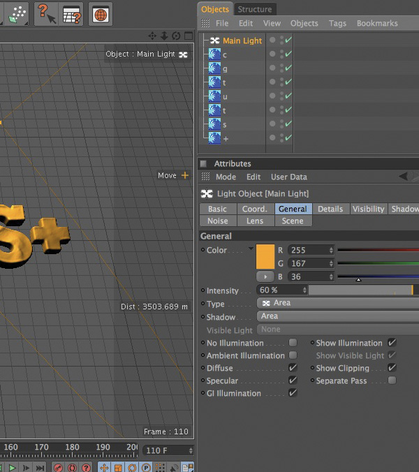
Rename the first one to ‘Main Light’. Click on the ‘General’ tab and change your settings to match the settings in the photo below.
Step 52
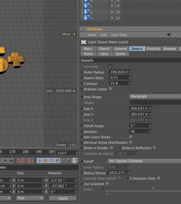
Click on the ‘Details’ tab and modify your settings to match the settings of the image below.
Step 53
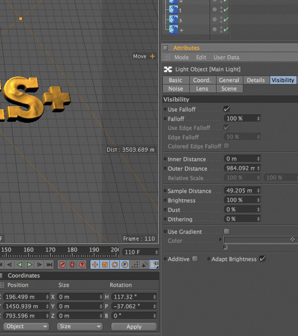
Click on the ‘Visibility’ tab and modify your settings to those that you see in the picture below.
Step 54
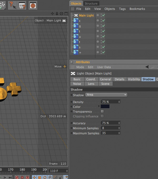
Click on the ‘Shadow’ tab and modify your settings to those that you see in the picture below.
Step 55
Position and rotate your ‘Main Light’ accordingly.
Step 56
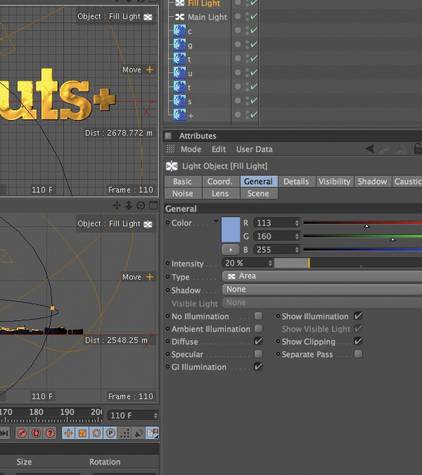
Select your second ‘Area Light’ and rename it to ‘Fill Light’. Click on the ‘General’ tab and change your settings to match the settings in the photo below.
Step 57
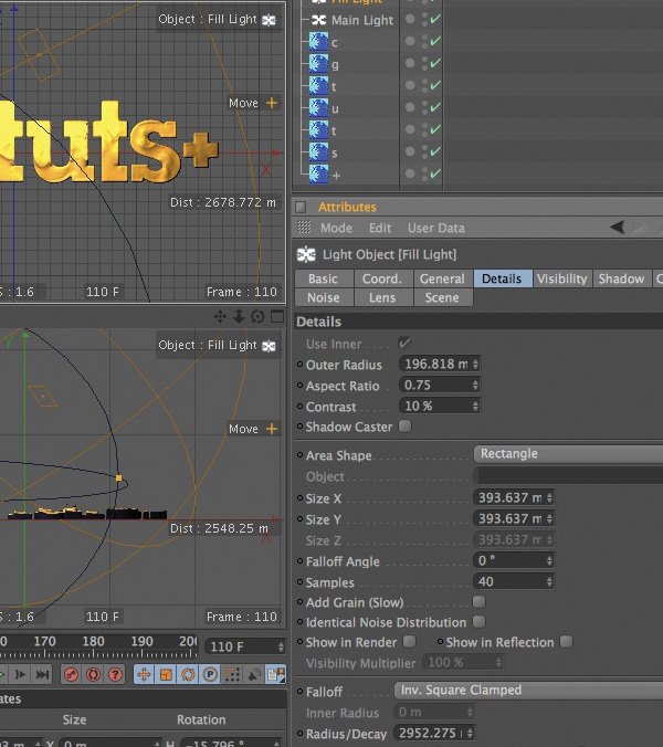
Click on the ‘Details’ tab and modify your settings to match the settings of the image below.
Step 58
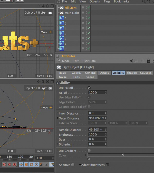
Click on the ‘Visibility’ tab and modify your settings to those that you see in the picture below.
Step 59
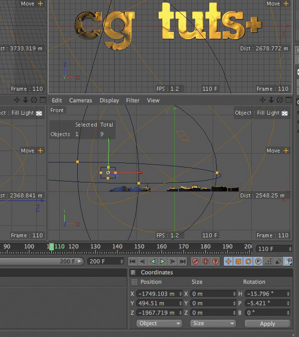
Position and rotate your ‘Fill Light’ accordingly.
Step 60
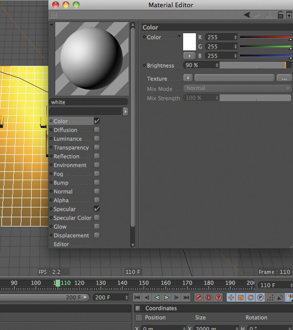
Add a ‘Floor’ object. Create a new ‘material’ and call it ‘white’. Change its color properties to R 255, G 255, B 255, and its Brightness to ‘90%’.
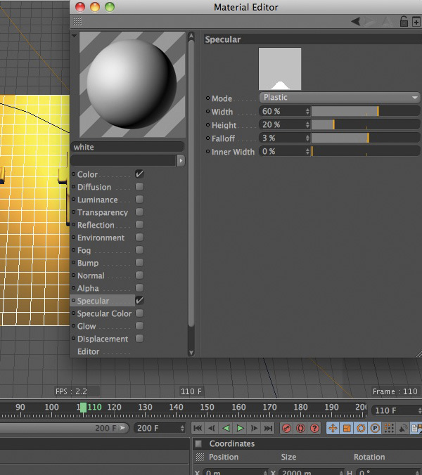
Step 61
Change its ‘Specular’ to the setting below. Add your ‘white’ material to your ‘Floor’ object.
Step 62
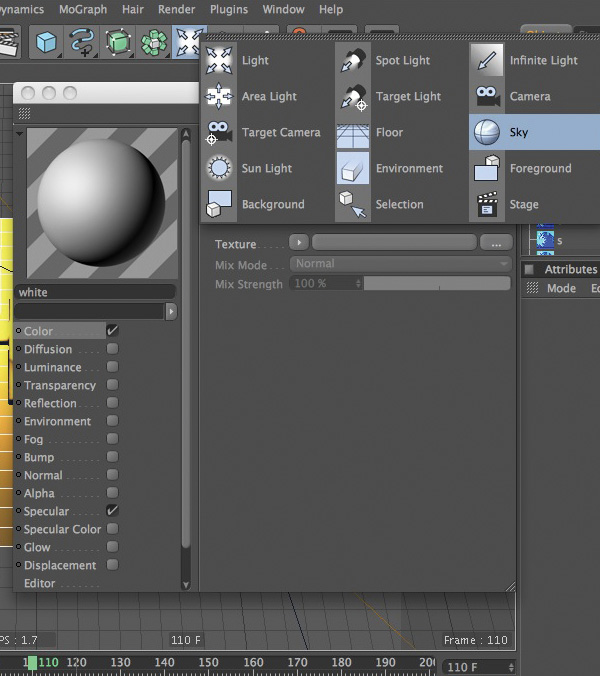
Add a ‘Sky Object’ to your scene.
Step 63
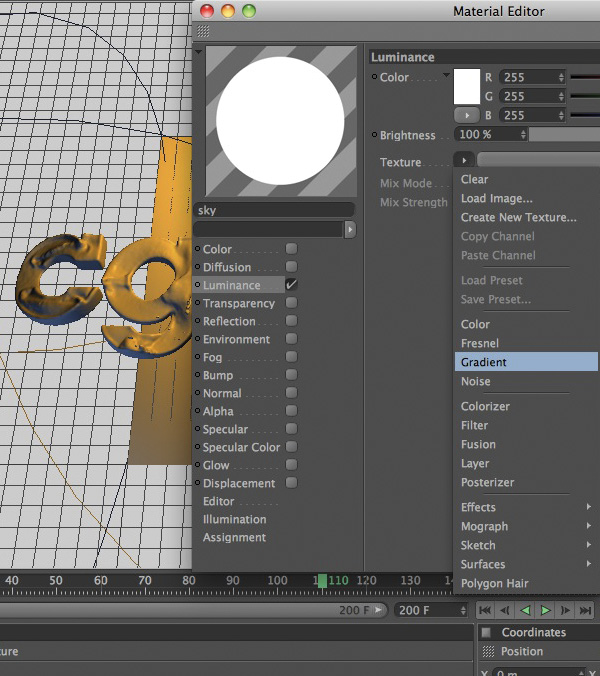
Create a new ‘material’ and name it ’sky’. Turn off both the ‘color’ and the ’specular’ channels and turn on the ‘Luminance’ channel.
Step 64
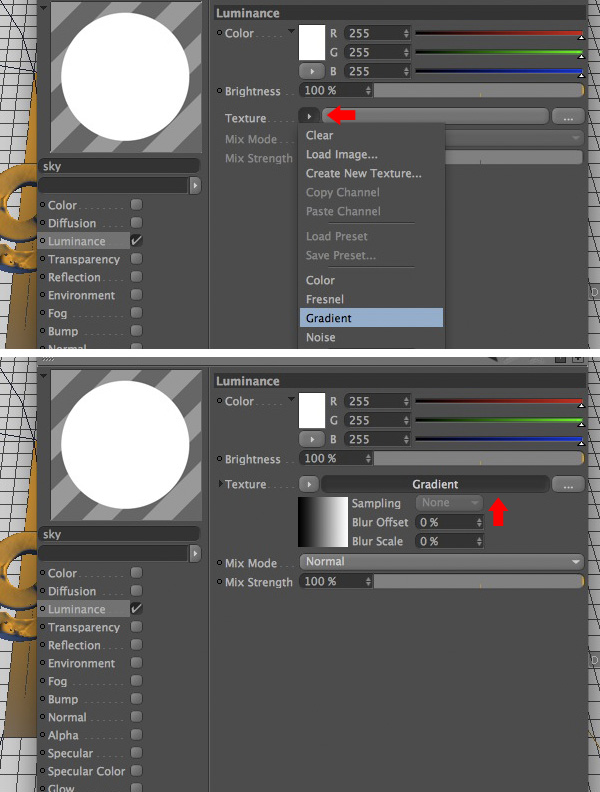
In the ‘Texture’ node click on the arrow to the right of it and select ‘Gradient’. Click on the ‘Gradient’ node.
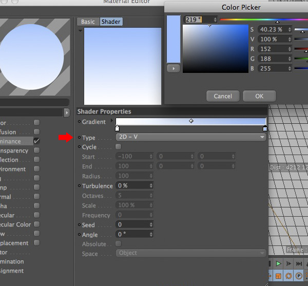
Step 65
Change the ‘Type’ of Gradient from ‘2D – U’ to ‘2D – V’. Modify your swatch colors to begin with pure white and end with a light blue. Change your ‘RGB’ values to match those in the image below. Click ‘OK’.
Step 66
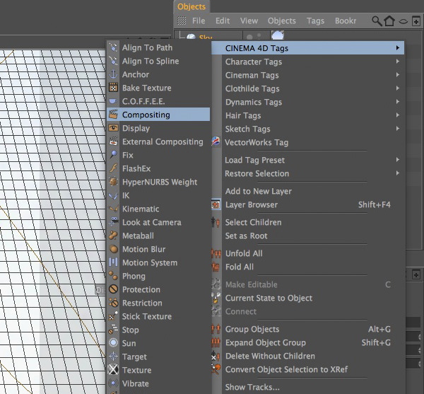
Add your ’sky’ material to the ‘Sky’ object you created. With your ‘Sky’ object selected, right click on it and add a ‘Cinema 4D Compositing’ tag.
Step 67
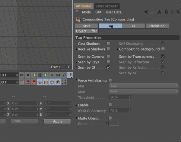
Click on ‘Tag’ tab and match your settings to the ones below.
Step 68
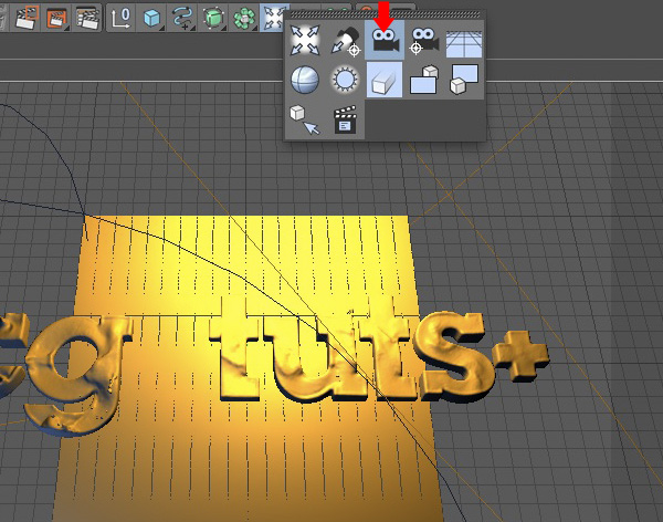
Add a ‘Camera’ to your scene.
Step 69
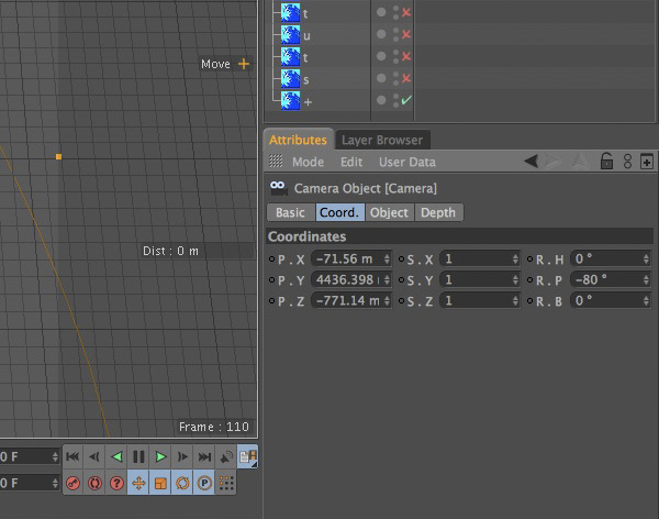
Move your ‘Camera’ to a position where your animation is centered and you can see some depth on the letters of your logo. These are my settings below.
Step 70
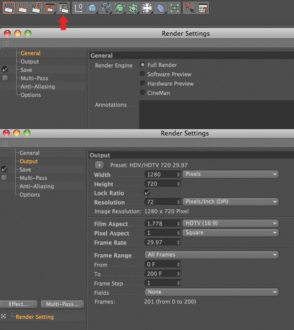
Open up the ‘Render Settings’ menu. Click on the ‘Output’ option and change the default setting to match the ones in the image below.
Step 71
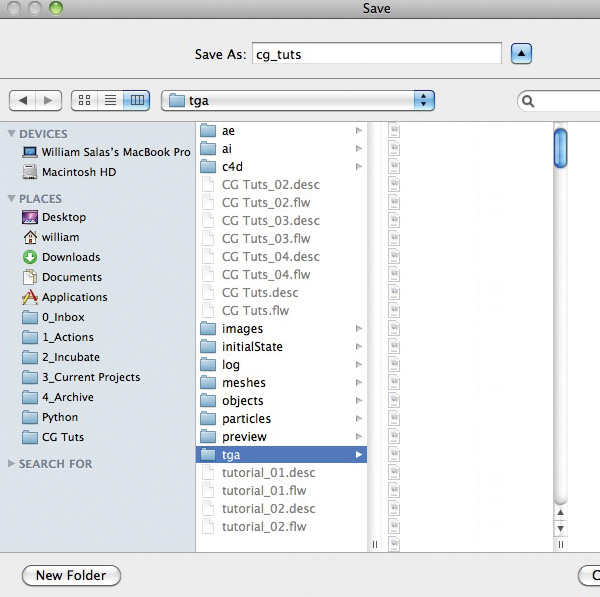
Select the ‘Save’ option. Navigate inside your main ‘cg_tuts’ folder and click on the ‘tga’ folder. Name your file appropriately and hit ‘Save’.
Step 72
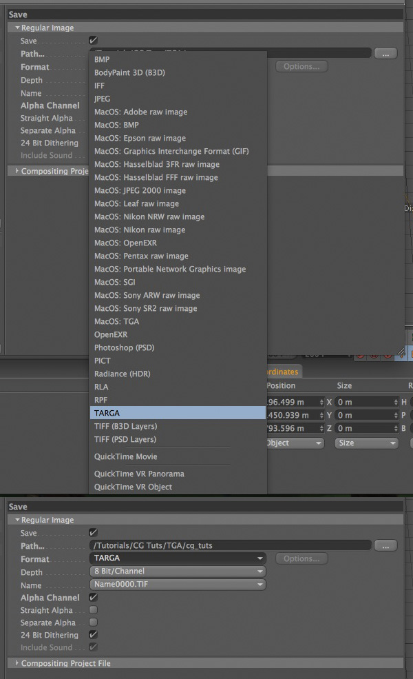
Change the ‘Format’ option to ‘TARGA’. Add a check mark to the ‘Alpha Channel’ option.
Step 73
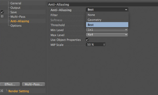
Click on the ‘Anti-Aliasing’ option and change it from ‘Geometry’ to ‘Best’.
Step 74
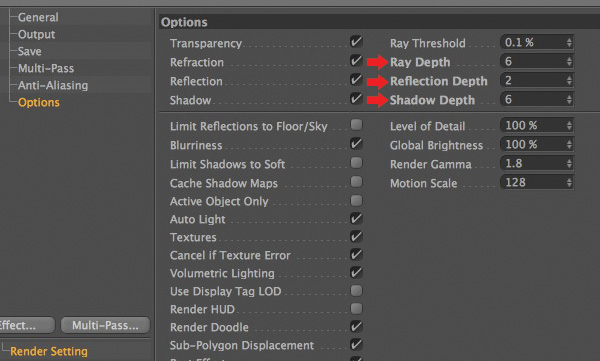
Click on the ‘Option’ option, and change the ‘Ray Depth’, ‘Reflection Depth’, and the ‘Shadow Depth’ to the appropriate values below.
Step 75
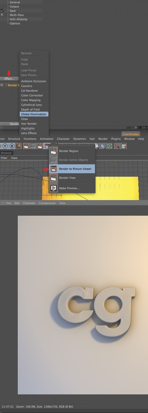
Click on the ‘Effect’ button and add a ‘Global Illumination’ effect. You are now ready to render. Hit ‘Shift + R’ or select the ‘Render to Picture Viewer’ icon to start your render. Depending on how fast your machine is this can take several hours even days. Mine took around 12 hours.
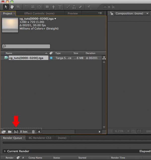
Step 76
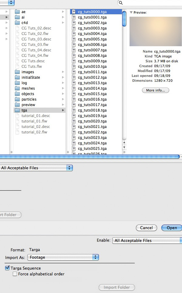
Fire up After Effects. Import your ‘TARGA’ sequence that you rendered out from Cinema 4D. Make sure that ‘Targa Sequence’ is checked.
Step 77
Drag you imported TGA Sequence onto the ‘Create a new Composition’ icon.
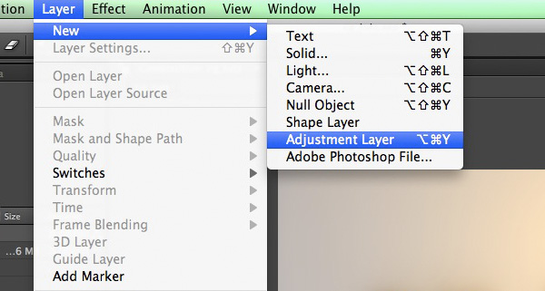
Step 78
Select ‘Layer’, ‘New’, ‘Adjustment Layer’.
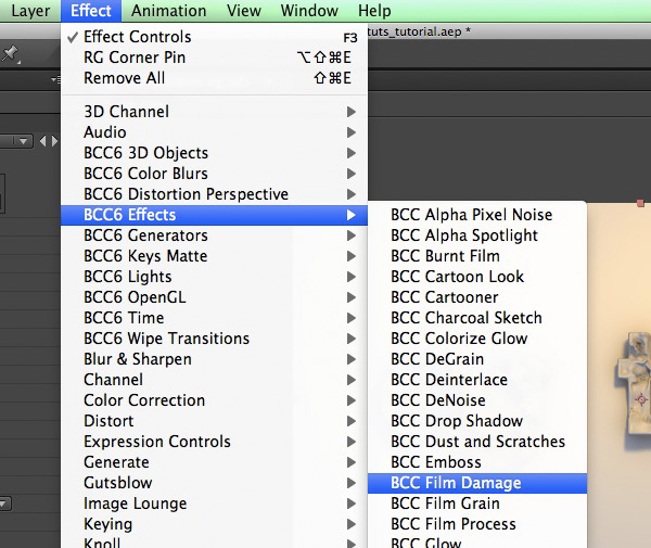
Step 79
Rename your ‘Adjustment Layer 1′ to ‘Effects’. Navigate to ‘Effect’, ‘BCC6 Effects’, ‘BCC Film Damage’.
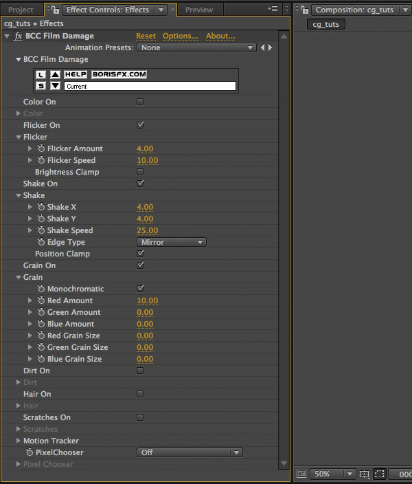
Step 80
Change your settings to match those of the image below.
Step 81
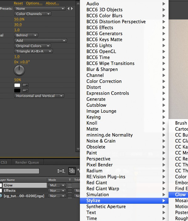
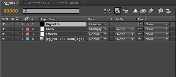
Create another ‘Adjustment Layer’ and rename it to ‘Glow’. Change its ‘Threshold’ to ‘50.0%’ and its ‘Radius’ to ‘30.0′. Change its ‘Blending Mode’ from ‘Normal’ to Multiply’. You can play with these settings as you like to get the look you are going for.
Step 82
Finally, add a new ‘Black Solid’. Rename it ‘Vignette’ and change its ‘Blending Mode’ from ‘Normal’ to ‘Overlay’.
Step 83
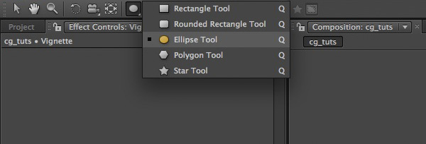
Change the default ‘Masking Tool’ from a ‘Rectangle’ to an ‘Elipse’. Double click on the icon to add a proportionately scaled mask to your ‘Vignette’ layer.
Step 84
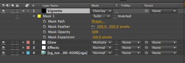
Change your mask settings to those of the image below.
Step 85
Add your composition to the ‘Render Queue’.
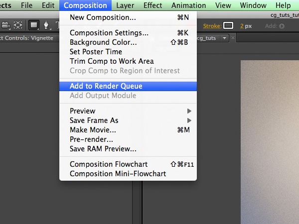
Step 86
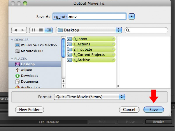
Click on the ‘Output To’ option and save your file wherever you would like it to be rendered to. Click on ‘Render’ and your done! Thanks for reading.
No comments:
Post a Comment