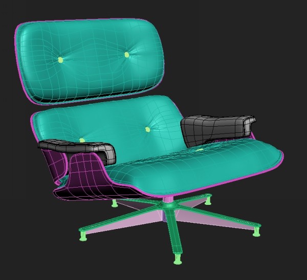
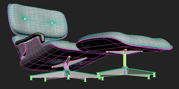
In this tutorial we are going to model a 20th century design legend, the
Eames Lounge Chair.
The reason I chose this particular object are its different shapes and
forms. It has both soft, organic pillows (with wrinkles) and a hard,
defined structure that holds it all together, making it an excellent way
to learn how to model both soft and hard structures.
This is a comprehensive tutorial with 98 steps, and will provide
complete instruction to modeling high-end 3D art for the intermediate to
advanced 3ds Max user.
Republished TutorialEvery
few weeks, we revisit some of our reader's favorite posts from
throughout the history of the site. This tutorial was first published in
June of 2009.
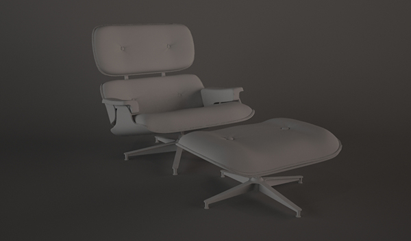
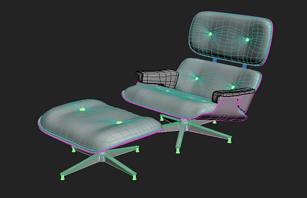
Final Effect Preview
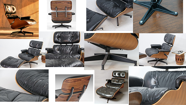
Gathering Reference
The first thing we need to do is find reference photos, blueprints
and drawings. I usually create a collage for this kind of modeling job,
so I don’t have to look through dozens of images.
I generally model these kind of models by eye, although I would
suggest using the right dimensions on models you will be handing to
other people, or placing in scenes. Another tip is to get one detail to
exact scale or size and then model everything else in proportion to
that. This will help you achieve relatively precise results in less
time.
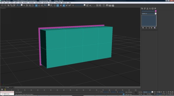
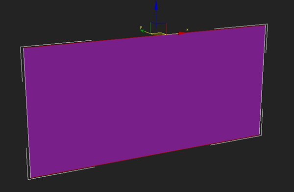
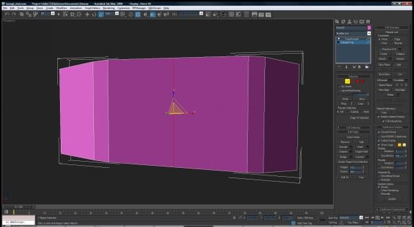
Creating the Upper Backrest
Let’s begin with the upper backrest. Create a box and subdivide it.
Then create a plane that is a bit bigger, and set it behind the box. It
will be the wooden shell for the backrest.
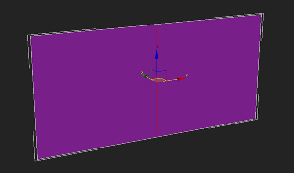
Step 1
Select the plane and subdivide it. To add these edge loops, select edges which will be crossed by the edge loop.
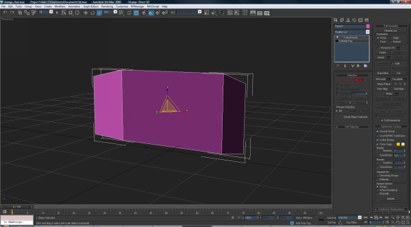
Step 2
Click Connect to add an edge loop. I will use this very frequently so
whenever I mention ‘Add an edge loop’ you should refer to this
explanation.
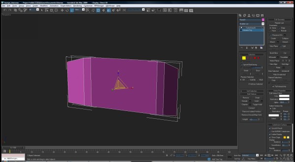
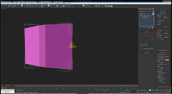
Step 3
Move forward the end vertices and scale them down slightly.
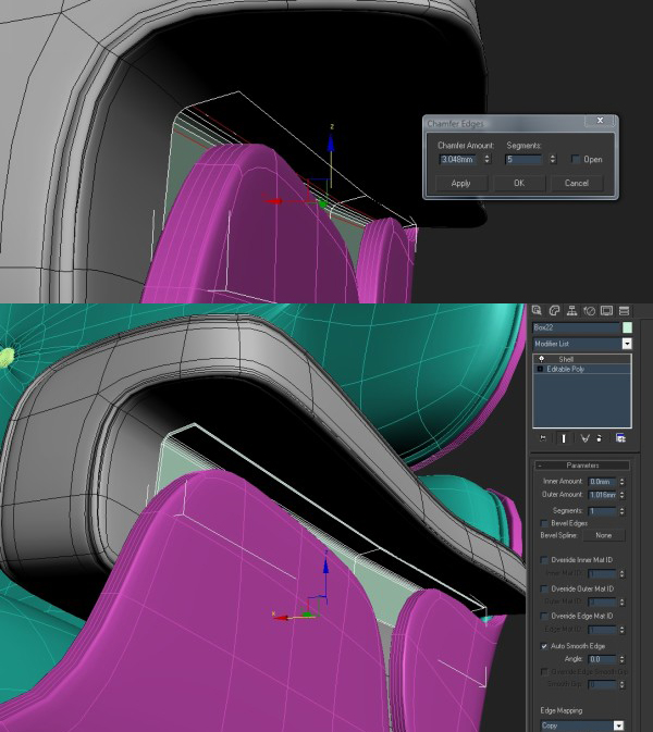
Step 4
Use the Chamfer tool to split the corner edges as shown.
Step 5
Add an edge loop vertically.
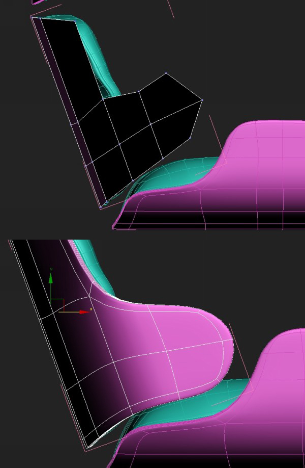
Step 6
Delete the right half. We will be using the symmetry modifier to get the other half in place.
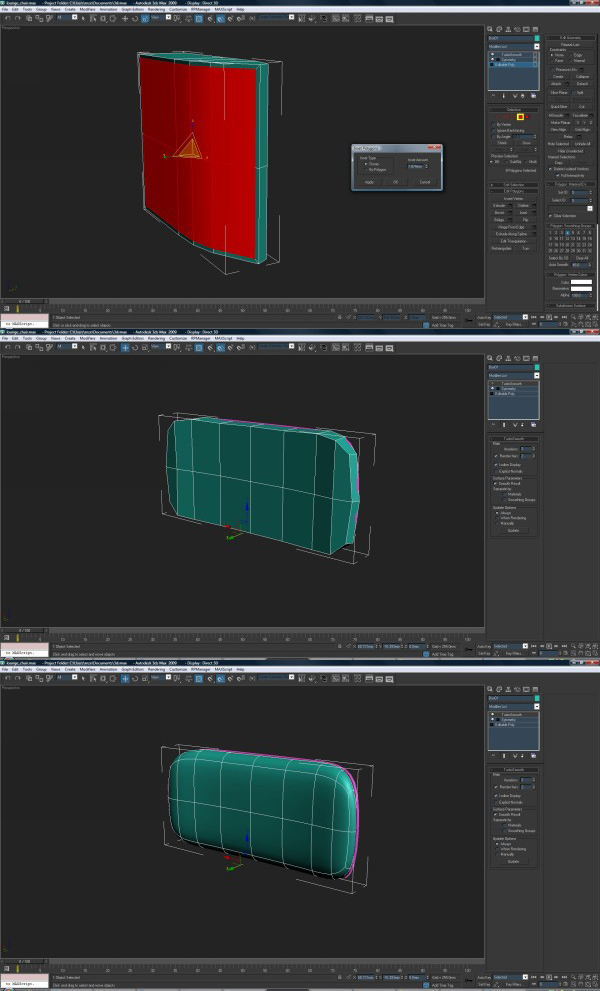
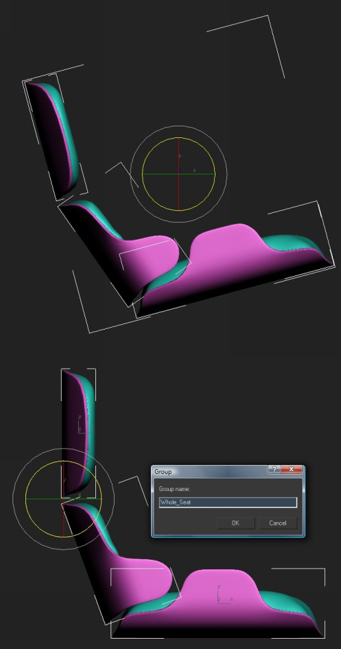
Step 7
On top of the symmetry modifier add a shell and a turbosmooth
modifier with these settings. This is just a way of optimizing the
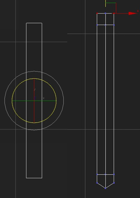
workflow, and a good habit to get into. If you want, you could also get
rid of one half vertically and use another symmetry modifier, so you
would need to work on just one corner. However, later on we will be
getting rid of these symmetry modifiers and giving each detail a bit
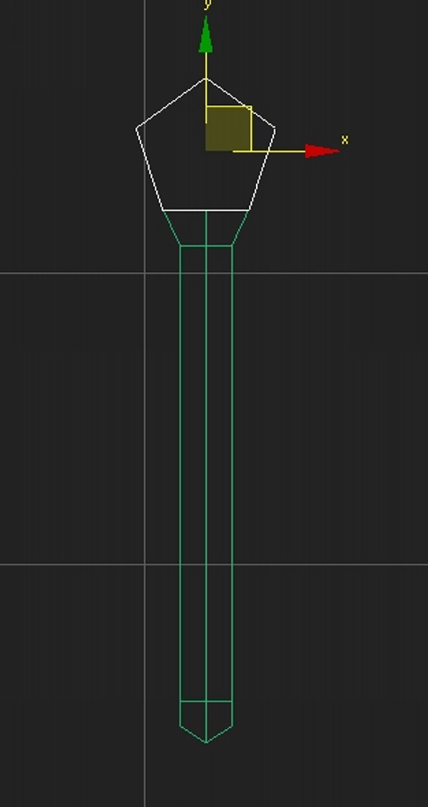
different look.
Below the first image you can see the result, but these settings may
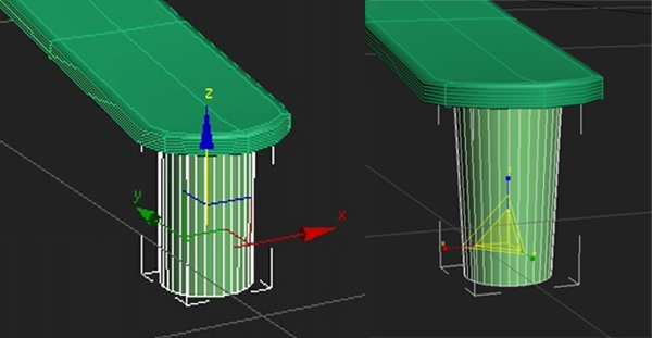
change as you go along. For example this wooden shell may be too thick
or too thin and so on.
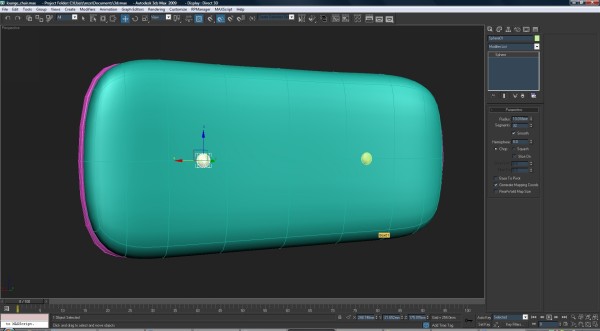
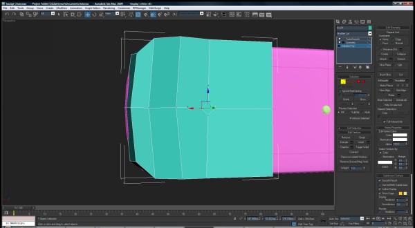
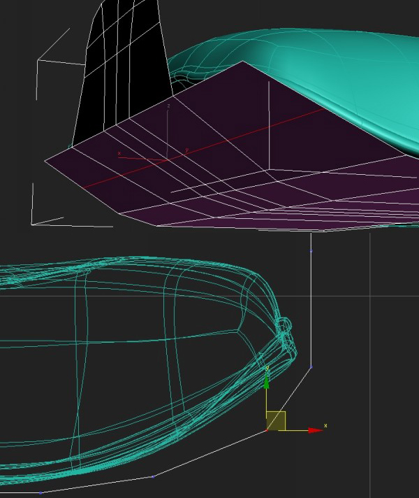
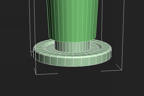
Step 8
Now we will be modeling the cushion and we will use the box we
created earlier. Select the right half of the box and delete it, then
copy the turbosmooth and symmetry modifiers from the wooden shell. You
may need to adjust the symmetry or maybe flip it. From the top view
adjust the vertices accordingly.
Step 9
Continue to add edge loops and adjust vertices.
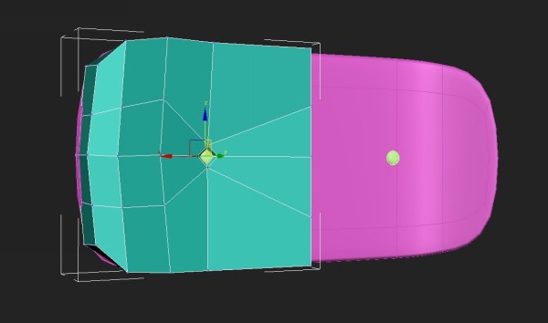
Step 10
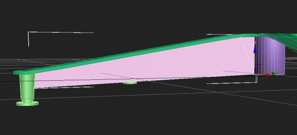
Select the polygons on the back of the cushion and hit ‘Inset’. This
is to add more definition so it looks like it’s attached to the wooden
back. Move vertices and polys accordingly.
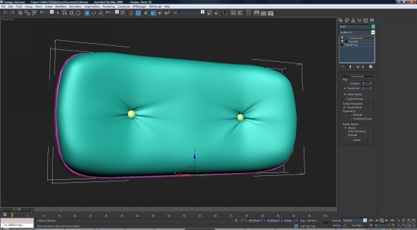
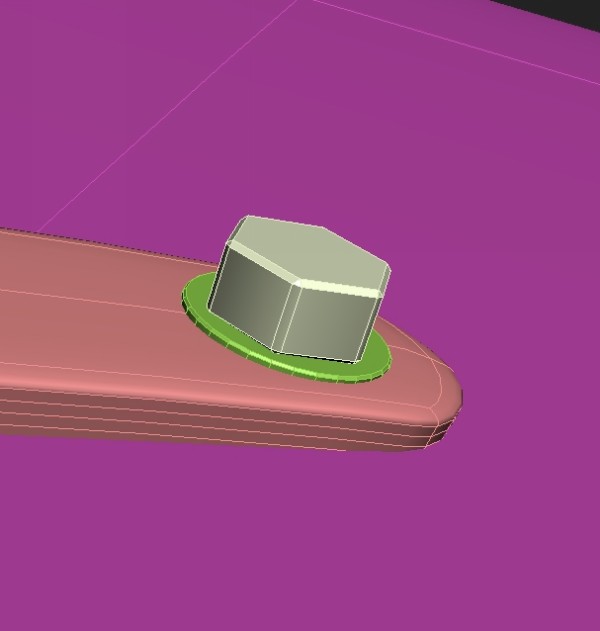
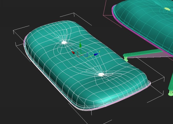
Step 11
Create a sphere and use the scale tool to squash it to create the
button. We will use the button to adjust the cushion model itself, so
place these two accordingly and sink them into the cushion model.
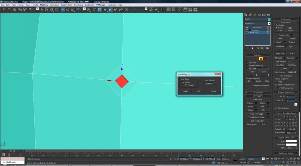
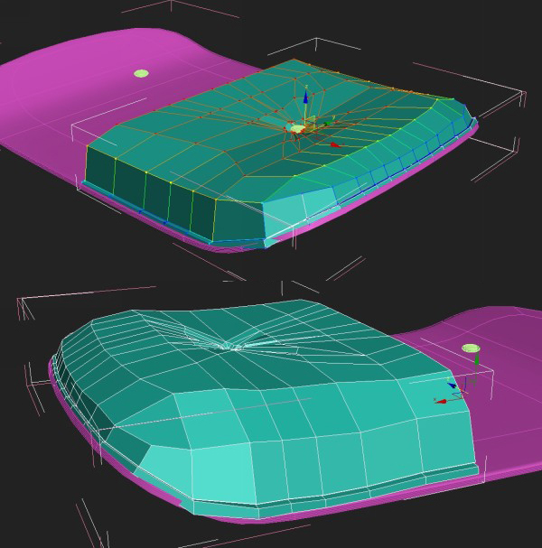
Step 12
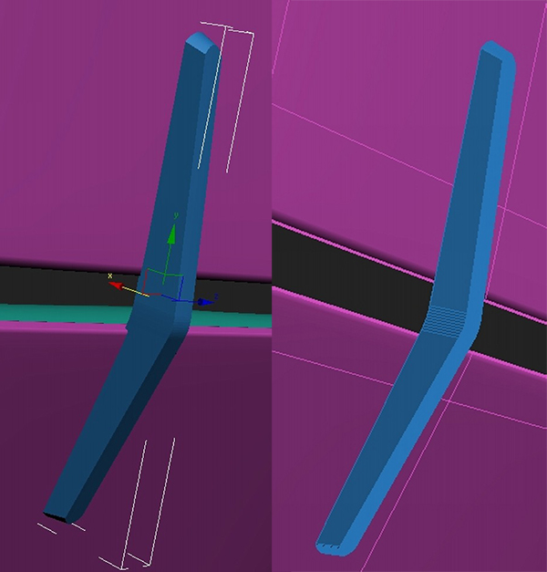
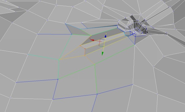
Select the vertex in the middle of the cushion and chamfer it, so you get these four vertices.
Step 13
Using the Inset tool, inset the polygon we just created and push it
inwards. You could also use the Bevel or Extrude tool to similar effect.
Step 14
Using the Cut tool create edges as shown. It is very important to
keep all these polygons four edged as they divide the best and the
smoothing is predictable and doesn’t have any glitches.
Step 15
Add two more edge loops in between the middle ones to add detail for
the creases and folds. Add one edge loop vertically to the right and
left of the indentation for the button.
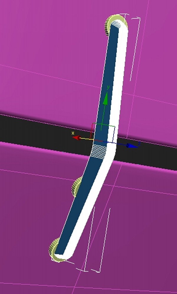
Step 16
Add two more edge loops, but now a bit closer to the center. Adjust them somewhat randomly to give direction for these folds.
Step 17
Round out the overall shape to give it a smoother look.
Step 18
Raise some of the edges to create a cloth-like effect.
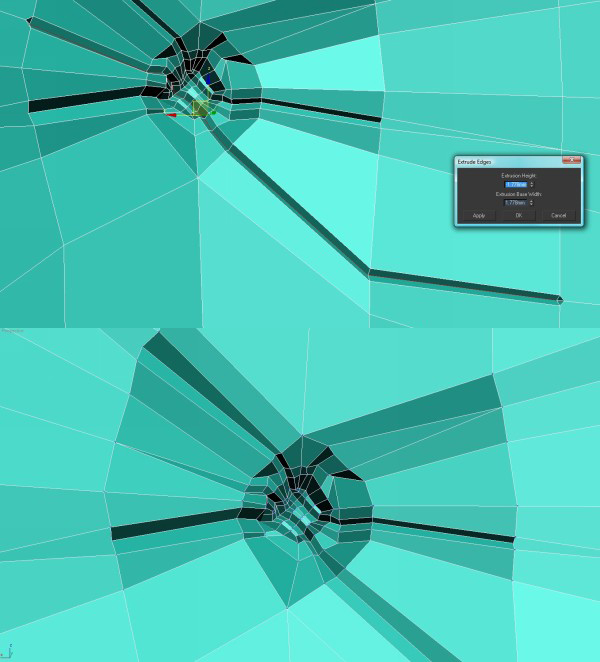
Step 19
To create additional cloth folds, create an edge loop and extrude it. Collapse the ends of the new polys.
Step 20
Repeat these steps several more times across the button hole to add more creases. The results are shown below.
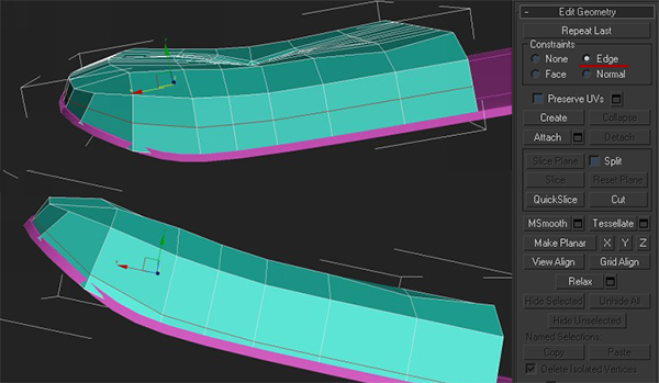
Step 21
Next, we will be adding sewn lines around the cushion that hold it to
the wooden base. To do this, add an edge loop on the side. Then, using
Edge constraints in the Edit Geometry rollout, move the new edge loop
closer to the sewing line. This is a very useful tool, and I use it
daily as it helps to move vertices along already made edges.
Step 22
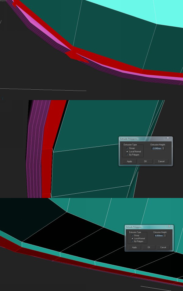
Select edges using Select Ring. Hold Cntrl and click on the Polygon
Subobject mode. This will select all polygons adjacent to the selected
edges. This is another useful technique I use very frequently. Using
the Extrude tool, extrude these polygons inwards, but don’t close the
Extrude dialog box. Hit Apply and then extrude it outwards. This will
create nice curvature and definition in that area.
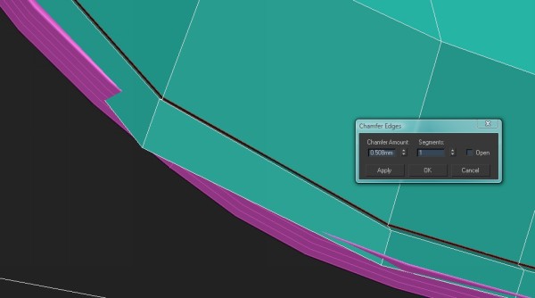
Step 23
Select the edge loop as shown below and use the Chamfer tool to
chamfer it slightly. This will add a more defined edge so that it looks
sewed on to the base.
Step 24
To finish the main modeling of the cushion, adjust the extruded areas until they look good.
Creating The Lower Backrest
Step 25
Holding down the Shift key, move both the wooden base and the cushion
downwards. This will create a copy of these objects. There is no need
to model everything from scratch as the chair has many parts that are
similar to each other.
Step 26
Select the new wooden base object and add another loop in the middle,
then move this down a bit. Select the lowest outer edge, and holding
the Shift key move it outwards. This is how it should look.
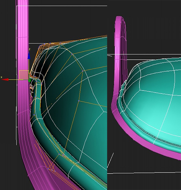
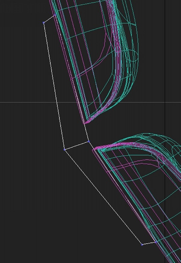
Step 27
Move the outer edge up a bit. Add two new edge loops crossing each other, like this.
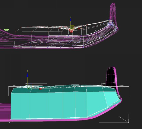
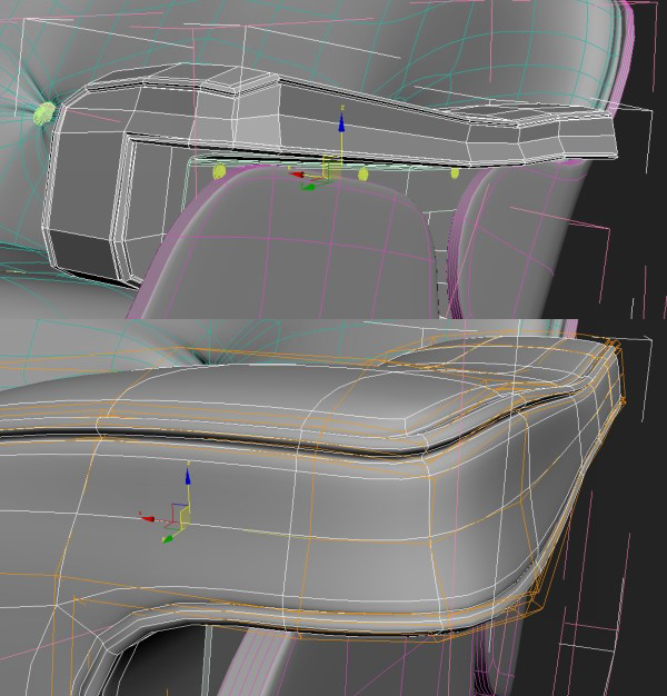
Step 28
Move the new vertices until it looks like the image below. In the
screenshot I have Shell modifier enabled, so that’s why it has that
thickness. The second image is how it looks smoothed with Turbosmooth.
Step 29
After these modifications I noticed that the cushion weren’t quite
sitting in right. I pushed them out according to the wooden base lines
like this. Also, make sure to check the back view as in my model some
vertices were sticking out.
Creating The Seat
Step 30
Then again copy second cushion and rotate it 90 degrees.
Step 31
Select the wooden base, go to Edge Subobject mode and again using
Shift key extrude left side edges. Then select the middle edge loop and
chamfer it. After that add an edge loop between these two new edges.
You could also use Extrude tool with height value set to 0.
Step 32
Then add another edge loop where I have shown and adjust vertices accordingly.
Step 33
Delete the cushion if you have copied it from the second backseat, as
its shape has been changed to flow along the second wooden base and
that won’t work for this part. It’s easier to adjust the first cushion
as it has a very generic shape. Place it in the middle of the base.
Step 34
Using the Scale tool, scale it according to the shape of the base.
After that, move the outer vertices closer to the edge of the wooden
base. I would suggest turning Turbosmooth on from time to time, just to
see how it is smoothing and to see if there are any glitches.
Step 35
Now select the top vertices on the cushion and lift them up to even
the surface out. This is to give it more of a volume as before it was
too flat.
Step 36
Select vertices along one of the sides and push them in to round-out the shape. Do the same for the other side.
Step 37
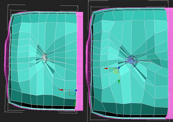
If you look from the top view you will see that the wrinkles are
squashed because of the scaling we did. To correct this select all of
the middle vertices and some around it and scale it to the sides until
it looks as shown.
Step 38
As the size of the model has increased but the amount of detail is still the same, add a few edge loops.
Step 39
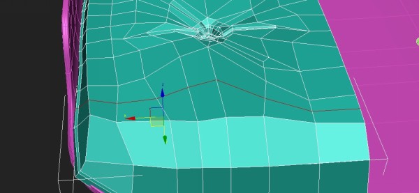
Select the base of the seat and add another edge loop. Push it
outwards to round it out. I did this because I noticed that the seat and
the leg rest both have rounder shapes to hold the cushion in.
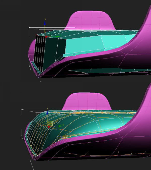
Step 40
Adjust the part that touches the extruded base. You need to push them
according to the form of the base, so that it looks like there is
pressure for the cushion to stay in place.
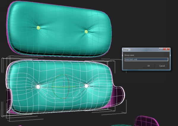
Step 41
Unhide all other parts. We need to group them for easier scene
management, and we also need to name them. I named the second back seat
‘lower back seat’, for example. It’s up to you how to name you objects
as long as it makes sense to you.
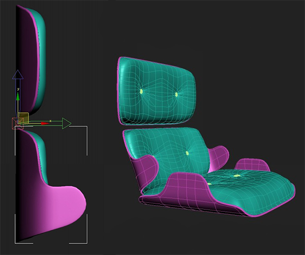
Step 42
After that I adjusted the Pivot point of the lowest back seat. This
is for easier rotation and placement of these objects. After placing
these objects correctly, it should look as shown.
Step 43
At this point I noticed that the lowest back seat wasn’t matching the
photos. To correct this, I selected vertices that didn’t match and
moved them to the right place. This is what I got.
Step 44
Group all of these objects and name the group (I called it
‘Whole_seat’). Rotate it so that is in the same position as the photo
references.
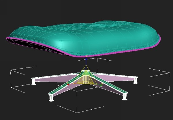
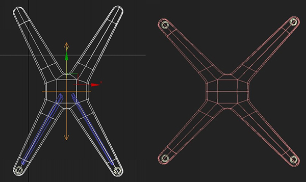
Creating The Chair Leg
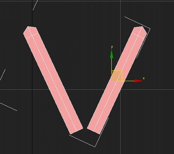
Step 45
Next we will create the main leg for the chair. Start by creating a
plane and then adding one edge loop vertically and two horizontally.
After that you will need to adjust them to shape, as shown.
Step 46
As the main leg has a five star shape, create a cylinder with five
sides and placed it next to the plane we just created. This will be
useful when copying the leg four more times.
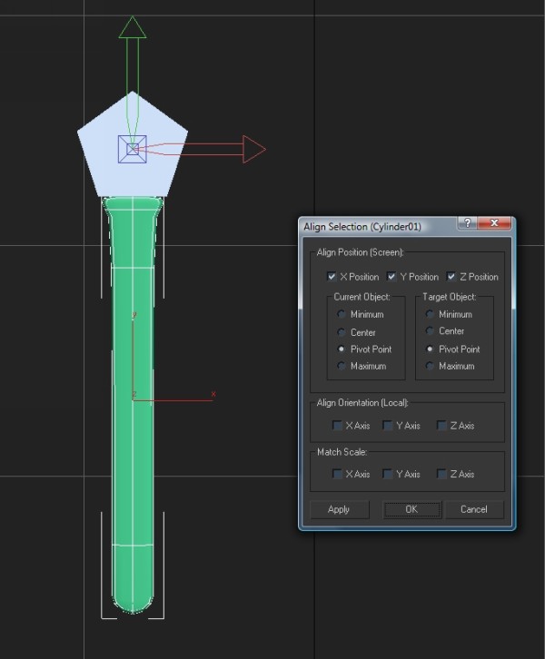
Step 47
Copy the Shell and Turbosmooth modifiers from previous models to the
plane and adjust them (I made the thickness amount smaller). Select its
Pivot and use Alt + A (Align tool) to align to the cylinder. This is so
you can easily copy and rotate it.
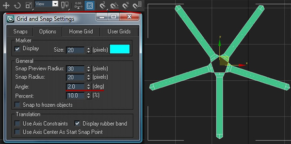
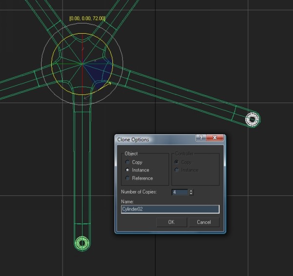
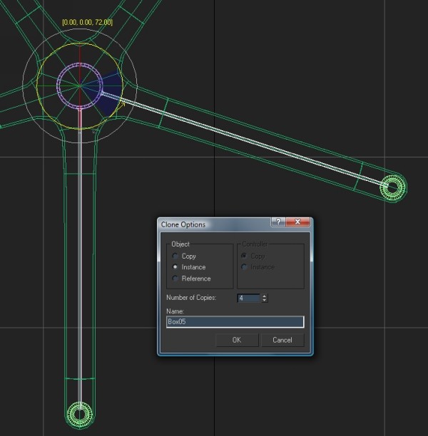
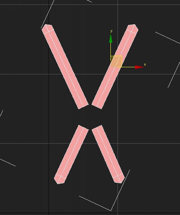
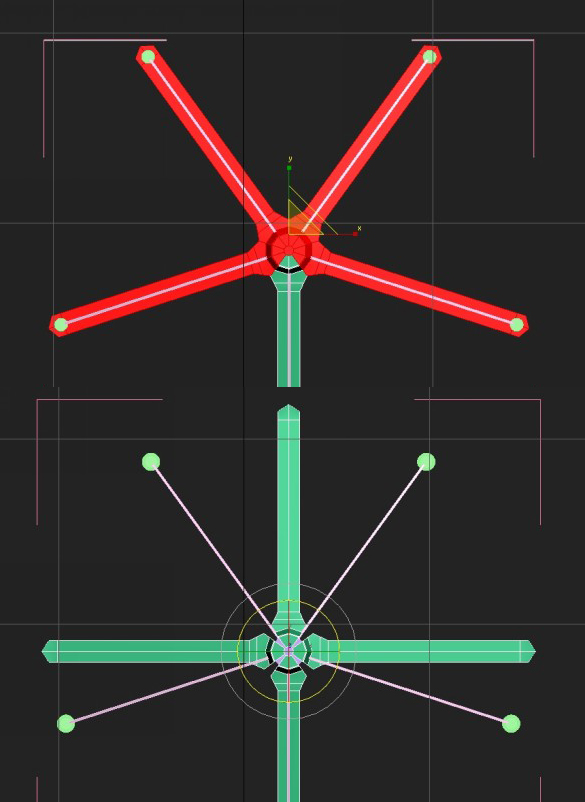
Step 48
To copy it four more times you need to copy it by 72 degrees, and you
need to do it precisely. Right-click on the Angle Snap button and make
the Angle value 2. This will angle snap it by every 2 degrees. Rotate
it by 72 degrees while holding Shift, and in the Copy dialog box enter 4
copies. After that, combine all these copies into one object using the
Attach command. Be sure not to attach other objects if they have Shell
and Turbosmooth on top of them. If so, delete these modifiers first. If
you attach them with modifiers on them, they will be collapsed and
attached and will have another pair of Shell and Turbosmooth multipliers
on them. They will have double the amount of shell and smoothing on
them.
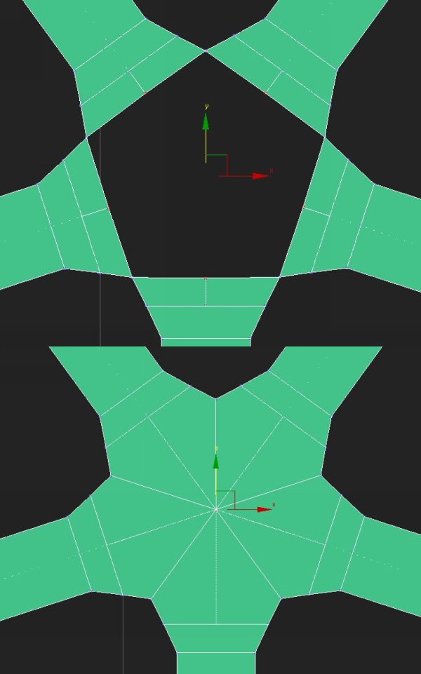
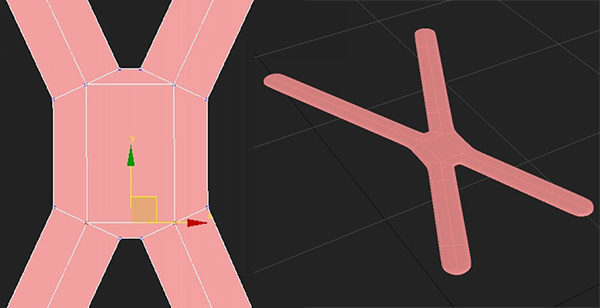
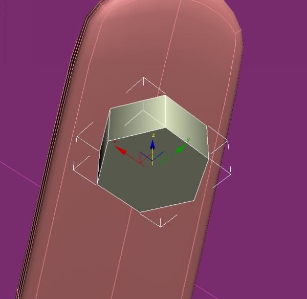
Step 49
Select 5 vertices as illustrated and click Collapse.
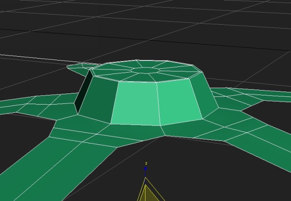
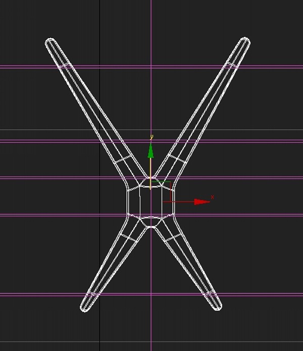
Step 50
Raise the center vertices up to mimic the photo reference.
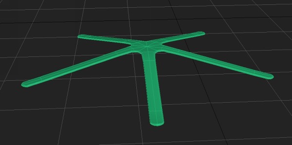
Step 51
Create a cylinder at the edge of one of these legs. Try to eyeball
its length according to the photos and scale the vertices at the bottom
of it to achieve the result below.
Step 52
Create another cylinder or copy the existing one underneath the one
you just created. Use extrude and inset to achieve this result.
Step 53
Attach these two objects together, and then align its pivot point to the center of the base that will hold them together.
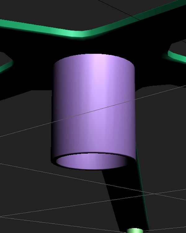
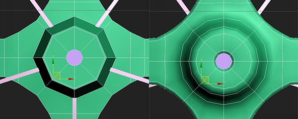
Step 54
Now create a cylinder, inset it a bit, and extrude it inwards.
Another method would be to create a Tube object from the Create rollout.
Step 55
Then create a box, and align it in between the tube and the cylinder
we created earlier. I added another vertex so that fits more nicely
there.
Step 56
Select the polygon at the end of the box near the cylinder, and
extrude it so it sinks into the tube. Then, using the Scale tool, scale
it in the top viewport so that it extends a bit. Add another edge loop,
and scale it down a bit to add the curvature needed.
Step 57
Now we need to copy this box four more times. For this I used the same technique I used for copying the legs.
Step 58
Extrude the top polygons on the leg, scale them in a bit, and inset them two times.
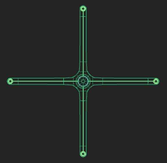
Step 59
Now we will be creating the part which is screwed into the bottom of
the chair and holds it to the main leg we created previously. Start with
a plane, subdivide it similarly to what we did for the main leg, and
then create a copy of it.
Step 60
Copy these two objects, rotate them by 180 degrees, and adjust the vertices so they are shorter than the first pair.
Step 61
Use the Bridge tool to connect these objects. Copy and paste the
Shell and Turbosmooth modifiers from previous models and adjust them.
Step 62
Select all outer ends of the model and scale them down a bit. After that move these ends further out from each other.
Step 63
Move it under the seat and rotate it to match the angle of the seat.
Create a cylinder and select the bottom edge loop (to do this select the
bottom poly and while holding Ctrl click on the Edge subobject mode
icon). Chamfer it using similar values as in this screenshot.
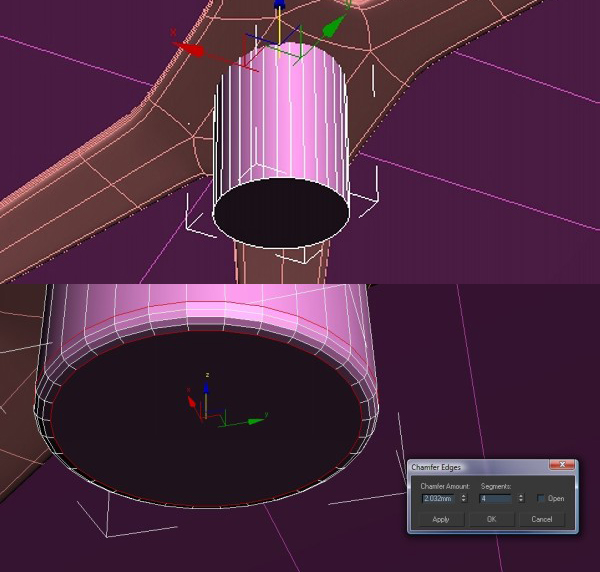
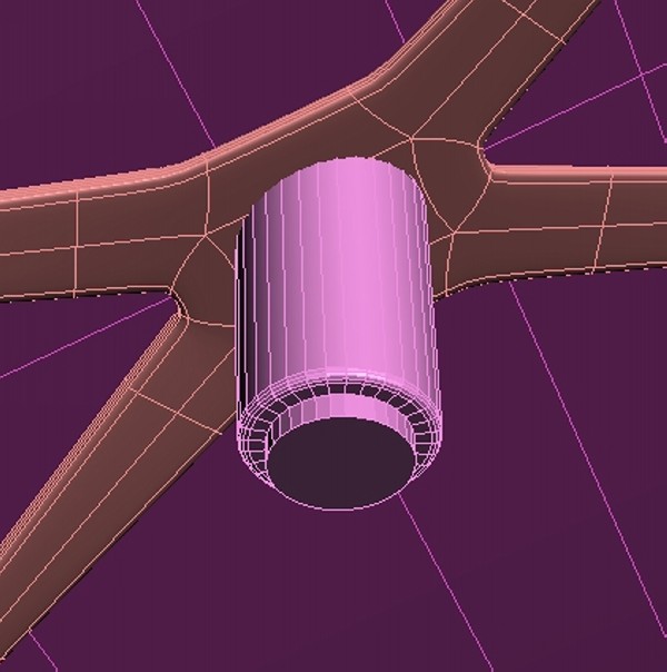
Step 64
Inset it and extrude it a bit.
This is how it should look together.
Step 65
Create a cylinder with five sides, then move it and rotate it to match the four ends of the part that holds the seat.
Step 66
Select all edges of this cylinder and chamfer them with a small
value. It will yield a nicer reflection if the rendering camera is below
seat level. Create another cylinder, but this time with about 30 sides,
and again chamfer all its edges.
Step 67
Copy them to all four ends of the object.
Step 68
Create a box and place it between the main cylinder and these five
sided cylinders (which are essentially screws). Adjust its vertices so
that they match this screenshot.
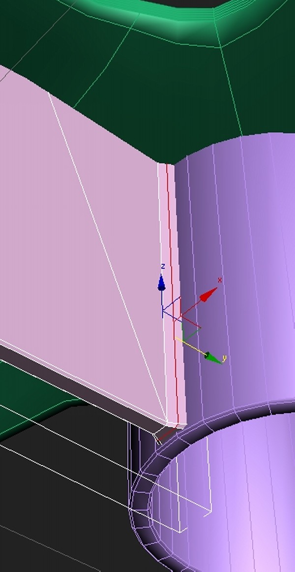
Step 69
Select the edge that is closest to the screw and chamfer it using similar settings to those show below.
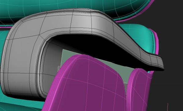
Creating the Arm & Backrest Details
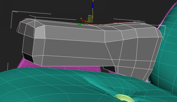
Step 70
Now we will create the armrest. Create a box and use extrude and edge loops to create a shape similar to the one pictured below.
Step 71
Add edge loops near all three vertical edge lines.
Step 72
To smooth out the overall form, move the vertices at the edges so they are a bit rounder.
Step 73
Select the edge loops as illustrated. Select one edge and loop it.
If it is not going all the away around the object, select edges manually
until you get full edge loop. At the end you should have two full edge
loops selected.
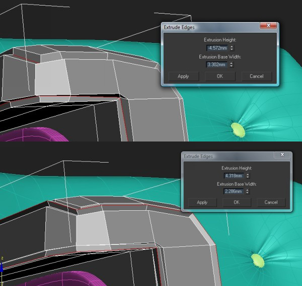
Step 74
Then use Extrude with negative values and click on the Apply button.
After that, make the extrude value positive (something similar to mine)
and click OK.
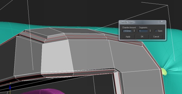
Step 75
Click Chamfer and use something similar to my settings.
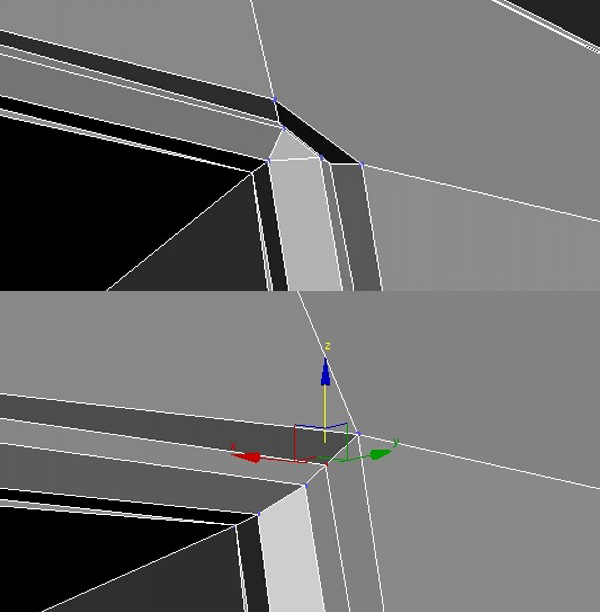
Step 76
After that you will notice that there are some problems on some corners. To correct them, collapse the vertices like this.
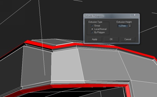
Step 77
Then select all the polys we just created. You could again select the
edge that is in the middle of these polys, and holding Ctrl, select
polygon Subobject icon. After that is done, extrude these polys a bit.
This will create the right amount of detail in that area.
Below is how it looks together with all models.
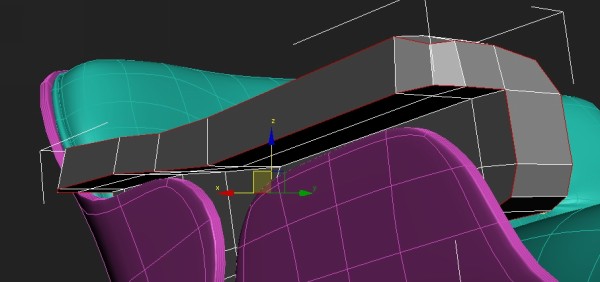
Step 78
Create a box with one edge loop in the middle, and adjust it so that it sits as shown.
Step 79
Add an edge loop in the middle of it, and move the top vertices out.
Step 80
Select the top and bottom edges that you pushed out, and chamfer them
using these settings. Do the same for the middle edge loop length wise.
Step 81
I modeled it slightly sunk in the chair, so move it out a bit to create some space.
Step 82
Add three cylinders with chamfered tops under that object we just
created. Copy it, and move it accordingly so we have two of these
objects separated evenly.
Creating The Leg rest
Step 83
Copy the top backseat and rotate it by 90 degrees.
Step 84
Using soft selection, select the top part of the vertices and move them up to give the cushion more volume.
Step 85
Copy the main chair leg and position it under the new cushion
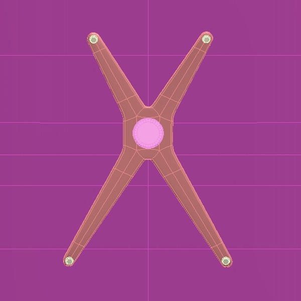
Step 86
As the leg rest base has a four star leg, we will need to modify the
one we copied from the chair. Select four of the five starred shapes and
delete them. Copy the one that is left 3 more times by Shift rotating
it by 90 degrees (making sure the pivot point is still in the center).
Remember to scale it down, as it is smaller than the main leg.
Step 87
Collapse all the vertices that are near each other.
Step 88
Delete all other parts of the leg except the one that you will copy. Select them and copy them three times by 90 degrees.
Step 89
Copy the part that is holding the bottom of the seat and move it
roughly to the center of the leg rest. We need to make all these shapes
the same length, so add a Symmetry modifier and make it mirror both the
shortest shapes.
Step 90
Adjust the box that will hold the structure together.
Step 91
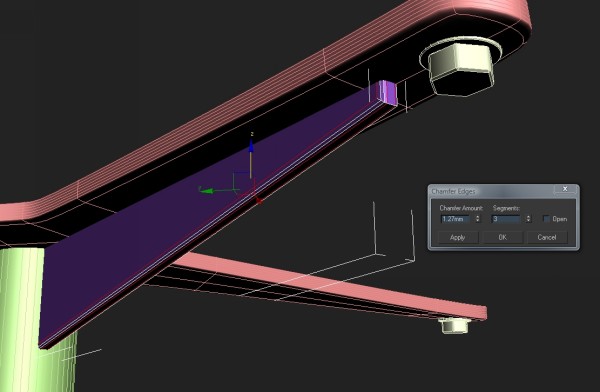
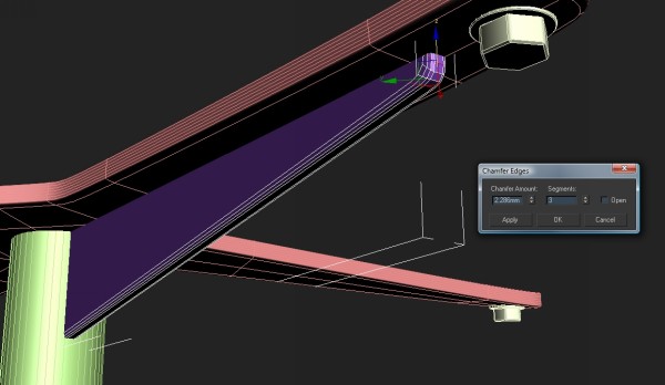
Smooth out the boxes that hold it together by chamfering the side edge and the one that is closer to the screw.
Adding Additional Details
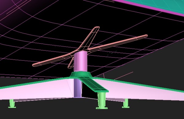
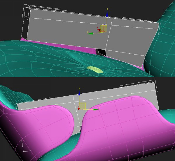
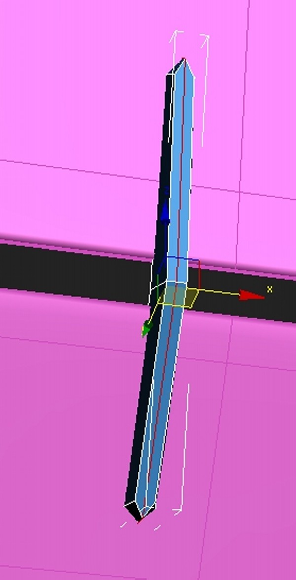
Step 92
Now you will create the steel angle that will hold the armrest.
Create a plane, and position it between the soft armrest and the wooden
chair base.
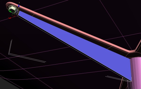
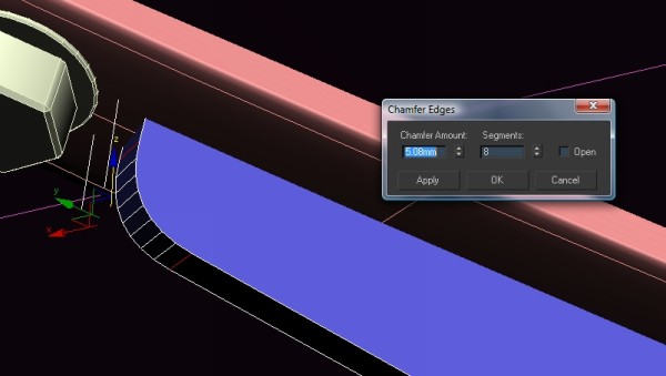
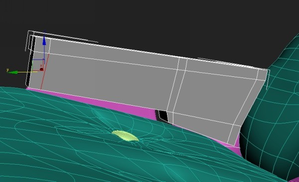
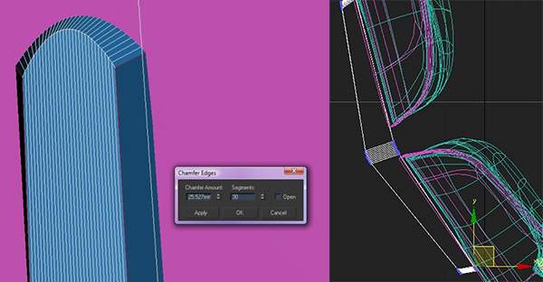
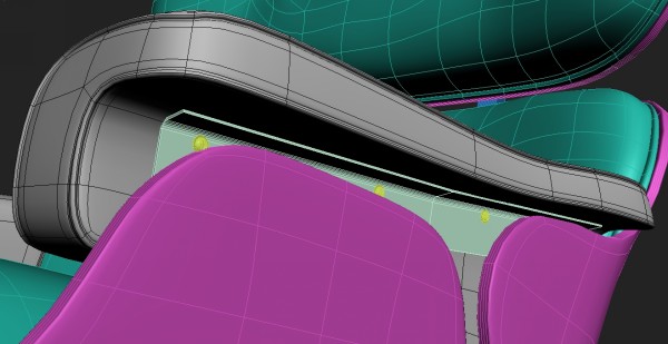
Step 93
Extrude the upper edge to the right using the Shift key. After that,
select the edge that is in the corner and chamfer it. Add a shell
modifier.
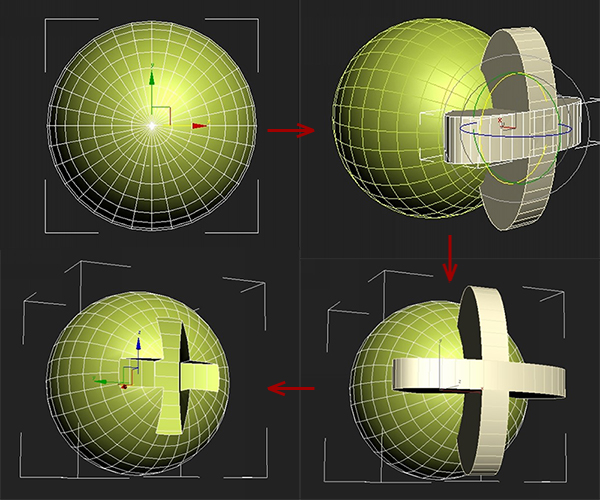
Step 94
Next you will need to create a screw head. Create a sphere and a
cylinder. Squash the cylinder, copy it and rotate it by 90 degrees.
Attach both cylinders together. Using the Boolean tool cut out the cross
shape into the sphere.
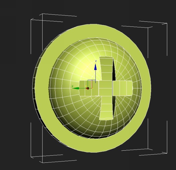
Step 95
Squash it a bit flatter and add a cylinder at the end of it.
Step 96
Copy these screws accordingly. Then copy all these objects to the other side.
Step 97
Everything is almost done, but first we need to add a bit of
variation to the model. This is because most of it was made using
symmetry, so it looks pretty generic and computer made. To add the
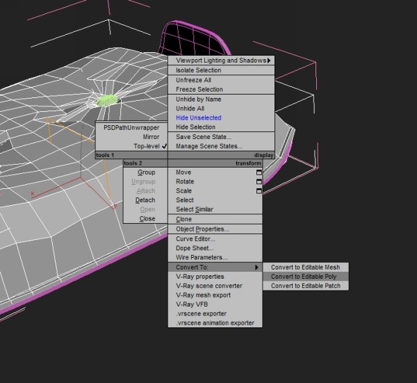
natural variation, we need to collapse all cushions so they don’t have
Symmetry modifiers. Cut out the Turbosmooth modifiers and collapse the
model to Editable Poly. Paste back the Turbosmooth. Do this to all the
cushions and armrests.
Step 98
Using Soft selection, move some of the wrinkles around to make it
more random. Make some parts smoother or more extruded and visible. As
for armrests, add one edge loop between those sewing seams and then push
it in to give the impression that these lines are holding it together.
Don’t make these identical for both armrests, as it will look copied.
Final Result